MAXCOIN CLEAN ENERGY PROPOSAL
LICENSE
Copyright (C)  DECENTRALIZED CLIMATE FOUNDATION A.C.
Permission is granted to copy, distribute and/or modify this document
under the terms of the GNU Free Documentation License, Version 1.3
or any later version published by the Free Software Foundation;
with no Invariant Sections, no Front-Cover Texts, and no Back-Cover Texts.
A copy of the license is included in the section entitled "GNU
Free Documentation License".
DESCRIPTION
A system which can be a functional low scale proof of concept, by tracing real green energy data and representing it as tokens plus a proof of work that ensures the security and online operation consistency in an embedded hardware attached to a solar panel, we intend to achieve the original Satoshi vision (decentralization, and avoid double counting) and thus tokenize measured data with a small range of error.
MVP GOALS
The goal the following document is a proposal for building a proof of concept system with both hardware and software in a small scale model, this work is not only limited to that but also making some proposals that consider 3rd generation blockchains developments such as the blockchain trilemma , DAOs for management of trust and verification of Clean Energy datasets based on embedded open hardware technology, Liquidity Pools and Energy pools (Batteries) with real parity between the real energy and tokens representations of energy.
Following a fully free software as following the main philosophies of the Maxcoin Project (Max Current) and Decentralized Climate Foundation, and finally taking the DECA 2.0 protocol and Maxcoin’s Blockchain as base technologies and other second layer and multichain solutions, as base technologies that will ensure the security and scalability of the system.
COMPONENT DIAGRAM
 Img1. Maxcoin Clean Energy Component Diagram
Photovoltaic cells.
To take advantage of this energy from solar radiation, a photovoltaic cell is needed. Photovoltaic cells generate electricity directly from the electrons released by the interaction of radiant energy with the semiconductor materials of the photovoltaic cells. Sunlight is made up of photons, or beams of radiant energy. When photons strike a photovoltaic cell, they can be reflected, absorbed, or transmitted through the cell. Only absorbed photons generate electricity.
A photovoltaic cell is a device that is used to convert sunlight into electricity by the photovoltaic effect, that is, it is a transducer that converts the radiant energy of the Sun directly into electricity and is basically a semiconductor diode capable of developing a voltage of 0.5-1.0 V and a current density of 20-40 mA/cm2 depending on the materials used for its manufacture and the sunlight conditions. In the figure, you can see the electrical symbol of a photovoltaic cell in which the current flows from cathode to anode, that is, it flows internally from the semiconductor type N to type P (opposite to the direction of a diode) towards a resistance.
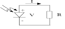
Img2. Electrical symbol of a photovoltaic cell.
Photovoltaic cell components.
Every modern solar cell usually consists of the following components:
-
Glass plate. It is one that allows light to enter the cells and protects the semiconductors in the cell from the elements.
-
Anti-reflective layer. It is the one that is between the glass plate and the semiconductor, and has the function of minimizing the loss of light by reflection.
-
The n-type semiconductor layer. It is one that has a concentration of excited electrons greater than that of the p-type layer, which causes the electrical charges of this layer to pass to the p-type layer, causing a potential difference with the other layer.
-
N-type and P-type semiconductor plate. It is the one in which the n-type and p-type semiconductors are placed and are linked through a path or pathway that acts as a conductor through which the electrons circulate to go from the n-type to the p-type semiconductor, generating an electric field in this cable.
-
The p-type semiconductor layer. It is one that has an electron deficiency, which attracts the excited electrons from the n-type layer, causing a potential difference to be generated between the two layers of the semiconductor.
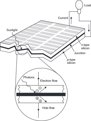
Img3. Main elements and functions of a photovoltaic cell.
Types of photovoltaic cells.
There are different technologies on the market, each of them has different characteristics. Silicon-based technologies currently account for 90% of global photovoltaic production and are the most dominant technologies. There are mainly three types of cells on the market according to the crystal type technology, all of them made of silicon.
Crystalline silicon.
It has an efficiency of 22%.
- Made up of a single crystal of very high purity silicon.
- They have very good performance and a useful life of up to 25 years.
- They are of the highest price in the market.
- Homogeneous blue color.
Multicrystalline silicon.
It has an efficiency of 18%.
- Made of silicon mixed with Arsenium and Gallium.
- Lower price compared to the previous one.
- Yield less than 20 years.
- Color with different shades of blue.
Amorphous.
It has an efficiency of 13%.
- Made of a thin layer of silicon.
- Performance and low prices.
- Homogeneous brown color.
Solar panel.
A solar panel, also called a photovoltaic module, is a set of cells electrically interconnected and protected against the elements, usually with a tempered glass front cover and a tempered aluminum frame that facilitates transport and installation.
A certain number of solar cells are electrically associated in the panel and the entire compact is protected by sealing it under vacuum, see figure.
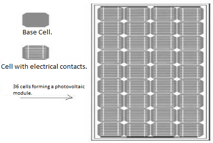
Img4. Diagram illustrating the composition of a solar panel
Electrical characteristics of a solar panel.
In the documentation provided by the manufacturer, as well as in the label attached to the solar panel, there is an electrical terminology that, in addition to general information on the product, the type of cell, the physical characteristics of the panel (width, length, thickness and the weight), the type of connection box, diagram or description with the distances of the fixing holes of the frame, what is called the I-V curve (intensity-voltage curve) of the solar panel appears. The standard test conditions (CEP) or STC (from English: Standard Test Conditions) are those laboratory conditions under which the power of a solar panel is measured and established. They correspond to a radiant light intensity of 1000 W/m^2 and a cell temperature of 25 ºC. Here, the maximum power (P max) that the panel can supply, the short-circuit current (Icc) and the open-circuit voltage (V oc) are measured. The knowledge of the three mentioned parameters P max., I cc, and V oc is enough to know the behavior of the panel in any operating condition defined by an irradiance value.
Environmental effects on solar panels.
The working temperature of the cells can be 20º to 25 ºC higher than room temperature. And, as in many electrical and/or electronic devices, excessive temperatures reduce effectiveness. As the cell temperature increases, the module current increases moderately while the voltage decreases significantly.
Classification of photovoltaic systems.
Depending on the functional and operational requirements of a system, there are isolated or independent systems, connected to the grid or hybrid with some conventional backup source, where different additional subsystems are required, such as storage, regulation and distribution, included in the latter that of protection.
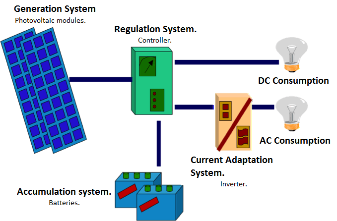
Img5. Basic diagram of an isolated photovoltaic system.
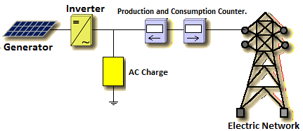
Img6. Basic diagram of a photovoltaic system connected to the electrical network.
Batteries.
Batteries, also called accumulators, are energy storage devices that convert stored energy into electrical energy through a chemical reaction. The figure shows the symbol used to represent a battery, accumulator or a battery of batteries. The most suitable batteries for photovoltaic systems are lead acid.
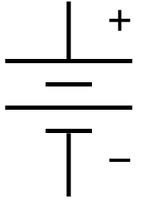
Img7. Electrical symbol of a battery or accumulator.
The behavior of a battery is fundamentally determined by two factors: the capacity in ampere-hours and the depth of discharge.
Battery capacity.
The storage capacity of a battery is defined as the amount of current that it will be able to deliver for a given number of hours at its nominal voltage and at a temperature of 25 °C. Capacity is designated in ampere-hours (Ah), and is the product of current in amperes and time in hours. Generally the capacity of a battery is in indices of 100, 20 or 5 hours; to refer to the capacity of a battery the letter C is used, for example the previous capacities are defined as C100, C20 and C5. The capacity is influenced by the temperature, if the temperature decreases the capacity decreases, but it is also worth mentioning that the high temperature causes a reduction in the battery life.
Battery types.
Batteries can be classified as primary or secondary cells. The first are used with the intention of being used only once, examples of these are carbon-zinc, alkaline and lithium batteries. The secondary cell stores electrical energy in a reversible chemical reaction, allowing the battery to produce current repeatedly, but the investment process does not occur 100% since there are losses due to heating and voltage difference some examples are nickel-cadmium, lead-acid and nickel-iron batteries.
Most photovoltaic systems use lead-acid batteries because of their low cost compared to other batteries.
Lead acid battery (Pb-Acid).
The commercial battery, in order to offer a practical output voltage, has several of these cells connected in series. Each cell is composed of several positive and negative plates, which have intermediate spacers. All plates of the same polarity, within a cell, are connected in parallel. The use of several plates of the same polarity allows increasing the active surface of a cell.
In it, the two electrodes are made of lead and the electrolyte is a solution of distilled water and sulfuric acid. When the battery is charged, the positive electrode has a deposit of lead dioxide and the negative is lead. When discharged, the chemical reaction that takes place causes both the positive and negative plates to have a lead sulfate deposit.
The most commonly used lead-acid batteries for photovoltaic applications are classified into two types: liquid batteries and valve-regulated batteries (VRLA - Valve Regulated Lead Acid battery).
Liquid Batteries.
They exist in an open version with lids that allow the water to be replaced and are low maintenance, but there are closed ones with valves so that possible gases can escape during excessive loads. Their advantages apart from the price is that they have fewer problems if they are overloaded. The disadvantages are the danger of losing the acid, a control of the water level is necessary and its typical short life is approximately 400 charge and discharge cycles. VRLA type batteries.
Gel batteries.
In these batteries, the acid is in the form of a gel. Their great advantage is that there is no longer a liquid that can be lost, they are closed. Corrosion is reduced and they are more resistant to low temperatures. Their life is much greater than the life of liquid batteries and compared to others, they are the least affected in cases of deep discharge. The disadvantages are a little higher internal resistance that reduces the maximum current flow, they are somewhat more delicate to charge and they carry a higher price.
AGM batteries.
They are increasingly being used in solar and wind systems. Its advantages in addition to those of gel batteries are high resistance in cold climates, its self-discharge over time is minimal, and it has the highest efficiency of all lead batteries (up to 95%). They have a low internal resistance that allows high currents. The disadvantage, apart from the higher price, is its higher vulnerability to deep discharges.
Controller.
The controller is the device in charge of controlling the processes against charges and discharges of the battery. Among its main functions are: Avoid battery overloads since once the battery is charged (EDC=100%), it does not continue with the charging process. This prevents the gasification process and temperature rise in the batteries. Anticipates over discharges in periods where there is insufficient sunlight, thus preventing the battery charge from being exhausted excessively and consequently reducing its useful life. Ensures system operation at the point of maximum efficiency.
The current controllers introduce microcontrollers for the correct management of a photovoltaic system. Its elaborate programming allows a control capable of automatically adapting to different situations, allowing the annual modification of its operating parameters for special installations.
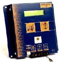
Img8. Controller.
The most important electrical characteristics of a controller are: the nominal voltage that indicates working voltage (12, 24, 48 V), maximum current that the controller will support, polarity and input and output connections.
Operation of a controller.
The controllers allow basing their operation based on the states of the load. Equalization. This response from the controller allows the automatic carrying out of accumulator equalization charges after a period of time in which the state of charge has been low, otherwise minimizing gassing.
Deep charge. After equalization, the regulation system allows charging current to enter the accumulators without interruption until the final charge voltage point is reached. Once this point is reached, the regulation system stops charging and the control system goes on to the second phase, floating. When the final charge voltage is reached, the battery has reached a charge level close to 90% of its capacity, in the next phase the charge will be completed.
Final charge and flotation. The final charge of the accumulator is carried out by establishing a zone of action of the regulation system within what is called the Dynamic Float Band. (B.F.D.). The BFD is a voltage range whose maximum and minimum values are set between the end of charge voltage and the nominal voltage + 10% approximately. Once the full charge voltage value of the battery is reached, the controller injects a small current to maintain it at full charge, that is, it injects the float current. This current is therefore responsible for maintaining the battery at full charge, and when no energy is consumed it is used to compensate for the self-discharge of the batteries.
Controller types.
There are two types of controllers, parallel and series. In low power installations, controllers are used in parallel and for high power, controllers in series.
-
Serial controller: The operation of this type of controller is to cut off the power supply from the generator (photovoltaic array) before it reaches the maximum battery voltage, thus avoiding reaching the battery overload level.
-
Parallel controller: The operation of this type of controller is to trigger power, with the purpose of eliminating the excess energy generated. The controller consists of a transistor located in parallel with the photovoltaic generator. For this type of controller, it is necessary to have a control circuit, which will be in charge of conducting the transistor depending on the battery voltage, that is, when the voltage is higher than a threshold (VSC) that it conducts and that when it is lower that it does not conduct.
Inverter.
The converters are devices whose function is to transform the voltage and characteristics of the intensity they receive, converting it to the appropriate one for the necessary uses, commonly the one used for photovoltaic systems is of the direct current type to alternating current (c.c./c.a.), since photovoltaic panels generate electrical energy in direct current and due to the type of loads for domestic use that exist, an element that performs this function is necessary. This type of converter is called an inverter.
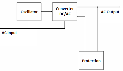
Img9. Basic scheme of operation of an inverter
- Oscillator: Circuit that generates the output alternating current frequency, made up of a high frequency ceramic resonator or similar, which is divided by the corresponding factor until the required value is obtained. This procedure establishes a high output frequency stability.
- Converter: The converter circuit receives the direct input voltage from the batteries and the frequency of the oscillator and thereby generates the alternating current output.
- Protection: This circuit is responsible for monitoring the consumption of alternating current to block the converter in the event of an excess.
MultiChain Miner Hardware/Software Especifications.
The requirements are an embedded computer with electronics interfaces to measure the clean energy and other types of sensors required, plus an ASIC/FPGA low consumption PoW Maxcoin Miner. On the Software side the requirements must for fill to have a Maxcoin Node connected to a Mining Pool, a IPFS node connected to the distributed database and a light wallet or way to interact with low storage consumption to the Ethereum Network and specifically with the DECA 2.0 Protocol.
On the Communications end, the requirements for the prototype the 802.11 can be enough but maybe in the future versions and to cover a wide range of area we should consider LoRAWAN with some mesh network features so that the system is even decentralized in the communications perspective.
The proposal can be a low energy consumption computer that has enough computing power to handle both the hardware the software specifications, such as Raspberry PI 4 B or even a Raspberry Pi Zero 2W if the laboratory tests prove its reliability.
NETWORK DIAGRAM
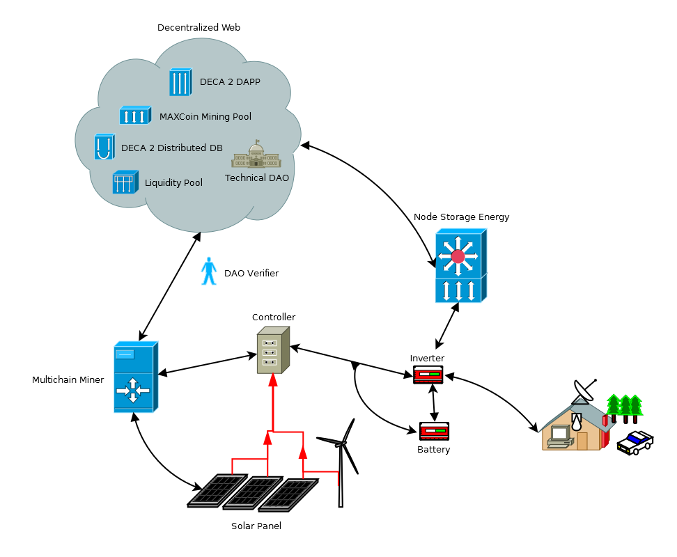
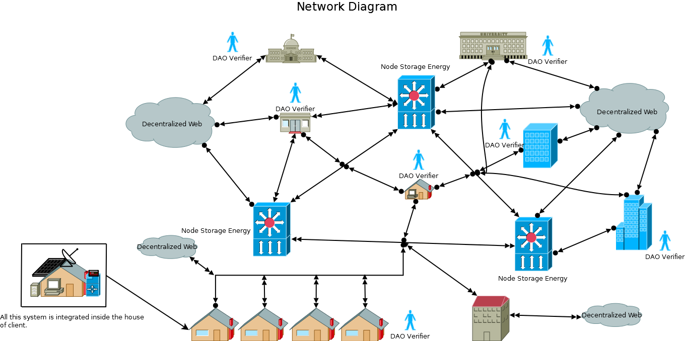 Img10. Maxcoin Clean Energy Network Diagram
The Img10. Describes the Maxcoin Clean Energy Network Diagram model based on multiple MultiChain miners (as described in the Components diagram Img4.) and Node Storage Energy Systems (Which can be any type of storage energy methods). The Goal of such topology is to create a decentralized distribution energy network where MultiChain Miners and Node Storage Energy Systems can interact in a free market for buying and selling energy in a decentralized way.
There can be multiple Use Cases, Market differences and Technical differences between the process of buying/selling and transmitting the energy from different endpoints of this network. Also, there are multiple variables that can be considered in such a network whether getting energy is cheaper from a shorter distance seller, or a node storage energy system has a more efficient and cheaper way to store the energy that can make it cheaper. There can be other variables to support more the decision-making on who and where someone wants to buy or sell the energy, based not only on technicalities to be price or energy efficient, but also to specific communities, technologies and others where we can have a truly decentralized free market.
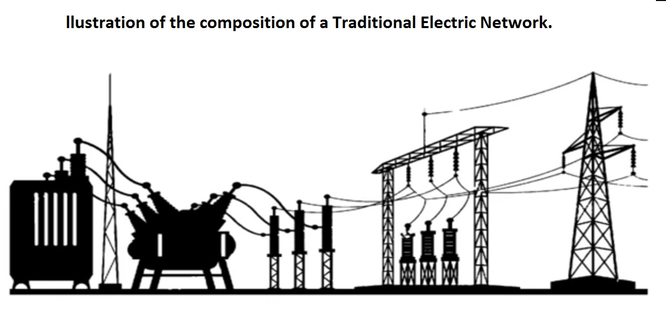
CURRENT ELECTRIC NETWORKS
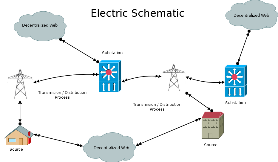 Img11. Electric Schematic
Fossil fuel energy.
They are an energy system that humanity has been using for decades, which has made it more accessible to one through all the resources that are possessed and that have been created over the years, allowing them to exploit their benefits to the maximum. It must be affirmed that with all the resources that are available, it is easier to transport, sell, market and even contain fossil fuels that at some point can serve as a means of energy.
On the other hand, fossil fuels have their disadvantages since after all these years of exploitation they have created damage to the environment through climatic changes, contamination of water, soil, and even air due to the gases that are released, in addition to the fact that large-scale conflicts have been created simply by having control of this means of energy since they are not found anywhere in the world. It is a highly coveted system.
This is just to mention a few aspects of fossil fuel energy. Another important aspect to mention is that this type of energy is mostly monopolised by large energy corporations that monopolise the world market and that together represent a great economic, political and even military power that influences the decision making in different countries and in our own lives.
In the different processes that electricity generated by traditional means, both renewable (wind, hydro, nuclear) and non-renewable (gas, oil, coal) are: generation, transformation and distribution, which will be explained in detail below, and in which solar energy is also involved as it is interconnected to the traditional electricity grid.
Energy Transmission and Distribution.
Once solar radiation is transformed into electrical energy through solar cells, the first electrical process is called transmission to a medium power transformer that in turn transports the generated energy to the substation for be processed, stored and forwarded.
This process is called Transmission and Distribution of Energy.
In order to minimise energy losses and to reduce the cable cross-section, the cables are transported at high voltage.
To understand a little more in detail the process of transmission and distribution of electrical energy, it is necessary to understand a little about reactive power, active power and apparent power.
We know that the union between active and reactive power is what is called apparent power, that total power that includes the electrical and magnetic phenomena.
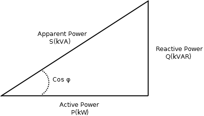
Img12. Aparent Power
The Apparent Power is defined by the multiplication between the voltage and the intensity of electric current.
\[S = I * V\]In such a way that for an equal value of power if the voltage is increased there will be less current passing through the cables because they are inversely proportional magnitudes.
\[I= \dfrac {S}{V}\]The Joule effect says that the power lost in thermal energy due to the conduction of electricity through a cable is equal to the resistance times the intensity squared, that is, the lower the resistance, the much less power will be lost in the form In addition, in this way it is possible to reduce the section of the cables (cable size) and in this way the weight that the structures have to support is also reduced.
\[P = I^2 * R\]For all this, the voltage is raised to transport high-voltage energy and then the voltage is lowered again when it is close to cities to bring that voltage level to normal levels for consumption and precisely the substation those places that allow the rise and fall of voltage. They are that key piece of the electricity transmission network.
 Img13. Electric Substation
When solar cells transform solar radiation into electrical energy, this is transferred to a transformer which increases or decreases the electrical voltage. In order for the energy to be able to travel to different areas, it is connected to a special location called a substation and begins to be transported, especially over long distances. The transmission lines are interconnected with other electrical nodes, which in turn have the function of increasing or decreasing the electrical voltage of the pylons in order to distribute the energy.
“Due to the achievable of this first version is to make a small scale model, we consider this section to be limited as this general description, it should be considered to further develop this section in the FUTURE ACHIEVABLE. The recommendations for these sections can be efficient distributed/decentralized smart energy grids and efficient ways to store big amounts of energy (for Node Storage Energy Systems proposals)” [name=P1R0]
USE CASE

Img14. Maxcoin Clean Energy Systems, Actors and Use Cases
The Use Case Diagram Img6. Describes most of the use cases for the Decentralized Energy Market operations, this diagram not only specifies the use cases but also the systems and the actors involved.
Note: The system requires Hardware and Network described in bouth the Compenent Diagram Img4. and the Network Diagram Img5. it also requires the DECA 2 Protocol and some other Ethereum based Protocols and Smart contracts which are being generalized as systems.
Systems involved
- Node Storage Energy: Any system which can store energy, send and receive (distribute) that is synchronized with the DECA2 Protocol. Each Node Storage should have its own equivalent of a Liquidity Pool Paired with the Energy token so that its tokens are equivalent with the total energy stored as watts.
Use Cases:
- Accepts Energy Storage Request Form a MultiChain Miner
- Update Measured Received Energy From a MultiChain Miner
- Accepts Energy Take Out Request From a MultiChain Miner
- Transfers Energy to the MultiChain Miner
- Maxcoin Clean Mining Pool: A system that is a Maxcoin Mining pool (Ideal to be a P2PPool) where the Maxcoin miner operations are easily to verify. This Maxcoin Miner is part of the MultiChain Miner and thus based on the mining operations should comply with the Clean Energy Generation and The Energy Token information. Proof of Work in a simple ASIC/FPGA (Low Power Consumption) might help us to provide enough proofs that the Clean Energy is being generated.
Use Cases:
- Stores Online Miner Time + Processed Hash Power
- Uploads Mining Data to the DECA2 Distributed Database
- Logs in with SBT (Each MultiChain Miner has an SBT as ID)
- Liquidity Pool: A System/Smart contract based on protocols similar to uniswap that the Node Storage Energy should have to be a market maker by pairing the Energy Token to the physical energy storage with other Tokens like DECA (governance) and/or Maxcoin.
Use Cases:
- The Multichain Miners and Liquidity providers “Gets a percentage per transaction”
- Swaps Tokens as Energy commodity with other types of tokens and proxies
- Provides liquidity DECA2/Energy Tokens (Default Payment to the Multichain Miner to add Liquidity)
- The MultiChain Miner “Gets Energy Tokens” when requested.
- DECA2 Distributed Database (orbitDB): Stores and Decentralize all the acquisition systems data like Measured Energy in both Miners and Nodes Storage Energy, SBT Data, Maxcoin Pool Data, DECA Measurements Data, and others.
Use Cases:
- Stores Energy Measurements
- Updates Measured Sent Energy
- Stores Received Energy Data
- Updates Measured Received Energy
- Verifies Data Integrity Related to the Miner
- Provides Access to the DECA2 DAPP
- Stores SBT Miner Data (Pool Data, Hardware Status)
- Updates Mining Pool Data
- Updates Miner HW Status
-
DECA2 DAPP: The DECA2 Decentralized Application is the main interface based on the DECA2 Protocol and other components required to for filling the Decentralized Maxcoin Clean Energy System Operations. The Actors are the end users of this system.
Use Cases:
- Gets MultiChain Miner Request from a miner candidate
- Approves MultiChain Miner Request approved by the DAO
- Set MultiChain Miner SBT attributes approved by the DAO
- Gets mint request from the Multichain Miner that the DAO approves
- Approved Minting (Ballot) for Mining Equivalent Energy Tokens
- Gets Payment Request Order from the Multichain Miner
- Gets Energy Measurement Data from the Distributed Database Registries
- Verifies Payment Request Order by the Technical DAO
- Gets SBT if they are a Miner or a Node Storage Energy system.
- Verify all data and vote, a process done by the Technical DAO
- Not Approved are some process to be done if rejected
- Votes module update To vote any system or module updates
- Mints DECA requires the DECA2 Protocol
- Mints Energy Token Usually delivered to the Liquidity Pool
- Fills Energy Request Usually done by the Node Storage System
- Stores DECA2 to the DAOs Vault to incentivize the DAO participants.
Actors involved
-
MultiChain Miner: Defined as both a Miner Hardware (which consist on generation and measurement system) and the Person that performs the mining process.
-
Technical DAO: Defined as both a group of People that handles the governance and also the system required for this process operations over Ethereum and DECA Protocol (Probably based on Aragon.org DAO developments)
SEQUENCE DIAGRAM

Img15. Max coin Clean Energy The Mining Sequence diagram
The mining process is represented by the Sequence diagram Img.7. In this diagram, we show the “Participants” previously described by the Img6 as systems and actors.
Note: This is a proof of concept model, there should be a deeper review on who and how to manage the Node Storage Energy Systems, if the Mining should either tokenize only the energy sent to the Node Storage System and/org also the energy that the MultiChain Miner Stores. In this example we consider that the tokens will be created once it is sent to the Node Storage Energy System so that we have 3 parameters for verification that the Energy is Clean, The Maxcoin Pool, The MultiChain Miner Data and the Node Storage Energy Measurements.
The Mining Process Description:
-
Multichain Candidate: The MultiChain Miner requests getting the Maxcoin Clean Energy System, this should be installed and attached to the Clean energy generator as described in the component Diagram Img4. and linked to the network as shown in the Network Diagram Img.5, The DAO verifies if the Miner Candidate Complies with the System and DAO requirements. If he complies, he will get the hardware and a SBT linked to the MultiChain Miner. the Process takes place at the DECA2 DAPP.
-
The Mining Process: Once the system is setup with the Green Energy Generator paired with the MultiChain Miner and following the models from the components and network diagrams, the Mining Process can start with the following states:
2.1 The Mining Process is a loop where the Maxcoin System starts mining PoW with low energy consumption, and connected to the Maxcoin Pool that records the Hash power and online time, the DECA Mining Process requires measuring Real Time Energy Generation and Storage/Usage Data which gets decentralized using the OrbitDB system and thus updating the DECA2 DAPP display information to the Technical DAO and other Actors.
2.2 While the Miner is operating the mining process, actions can be to either buy and sell energy to any Node Storage Energy System or even between different MultiChain Miners. In this sequence diagram, we interact with a Node Storage Energy system (NSE) for buying and/or selling clean energy.
a). If the MultiChain Miner wants to Sell an excess of its energy, the MultiChain Miner starts sending energy to the Node Storage Energy (NSE), after the Multichain Miner should record the Measured Energy Sent to the Distributed Database using the DECA2 DAPP. A similar procedure should be done by the NSE where it reports the received energy - energy looses during the transmission.
b). If the Miner wants to request payment of this energy from the Node Storage Energy for example Monthly, he should execute the request from the DECA2 DAPP, The Technical DAO then Verifies Data integrity related to the Miner and the NSE, Maxcoin Pool Mining Data, and The MultiChain Miner Hardware integrity.
-
If the payment request gets approved by the DAO: The Minting Mechanism gets executed by the DAO at the DECA2 DAPP, The Energy tokens are set as liquidity to the Liquidity pool represented by the Node Storage Energy that stores the energy received. Alternatively the Maxcoin Pool could also send the Mined Maxcoin to the Liquidity Pool of the Node Storage Energy for generating some yield to the Multichain Miner. Also, there should be some minted DECA/Energy Tokens or Maxcoin Tokens to pay to the DAO for handling verifications and operations.
-
If the payment request gets rejected by the DAO: The technical DAO should report the reasons and update the Status to the MultiChain Miner at the DECA2 DAPP.
c) If the MultiChain Miner wants to buy energy from the Node Storage Energy system it can use either DECA2 Tokens, Maxcoin or others that are paired with the Energy Tokens at the liquidity pool that represents the Node Storage energy, once the user gets the Energy tokens can request the energy equivalent to it to be sent from the NSE to the Multichain Miner once the process gets done, the Energy Tokens can be burned into the SBT to display the Clean Energy Consumption and even justify Carbon footprint reduction based on DECA2 Protocol.
-
-
Requesting the Tokens from the Liquidity Pool: The DECA2 DAPP and the protocol should incentivize as default to provide liquidity to the Liquidity Pools to create a more liquid market, therefore we consider in the model that they earn a yield in each transaction based on how uniswap or other Decentralized Liquidity Pools work. The Tokens in the Liquidity Pool should be assigned to the ownership of the MultiChain Miner and if he requests the Energy tokens or a Paired Token on the liquidity Pool the transaction request can always be executed.
Note we require to do a deeper research to make this either an option or a default because the impermanent loss can be an issue
FUTURE ACHIEVABLE
Considering that this system, its modeling and its implications are of high scale and complexity we consider that each model should be developed in phases, also the first tests should be done based on proof of concepts, low scale prototypes and further research. A small proposal for building next steps can be the following:
-
Development of DECA2 Protocol for filling or at least a base proof of concept code that can be paired with the protocol once it is ready.
-
Development of all the logic and decentralized software requirements (smart contracts, DAO, orbitdb, LP, etc…) with modularity and base operations functions so that it can be developed and improved gradually.
-
Development of a small scale system for the Components diagram and a simplified Network Model (MultiChain Miner, battery, solar panels and a small grid to share energy), that can interact with 2.
-
Further Research. And Laboratory reports after the prototype.
-
High Scale Prototype requires: Security Audits, Production Development and Deployment, Economic support and a community that is willing to use the Prototype.
CONCLUSION
There are multiple research documents, some of our research in which we find smart (pseudo)decentralized energy grids based technologies that want to implement blockchain y cryptocurrency technologies yet without understanding the real goal and philosophy of the cryptospace and thus have issues in the perspective of decentralization(double-counting) scalability and security. Other projects have multiple ideas and non development, and finally some that are too expensive and complex to implement that might require multiple years and research and thus economic resources.
The Maxcoin Clean Energy system is a complex system that requires a lot of resources, time and research to be developed. Our proposed model intends to provide a decentralized in all its components and layers, from software, hardware, infrastructure, decentralized finance, tokenomics to social organizations for operations such as DAOs. The advantage that such a system can provide is beyond a reliable and secure model, but also a change of paradigm on the way transparency, governance and social implications that can contribute for a free market of clean energy that can be considered as less corrupt by providing transparency in all its means and layers.
Searching for an efficient clean energy generation with the current intermittent methods and limited/expensive that its storage can be, specially for these types of energies (solar and wind powered) we are still far to be an alternative in what the production and storage of clean energy market price can be against the current energy prices of fossil fuels, but considering the advantages on the autodeterminance of societies that are dependent to geopolitical situations that can affect their reliability on such type of centralized energy systems, it should not be considered as an expensive alternative but an investment perspective that can enhance trust and reliability by building their communities stronger against external interest that can destabilize a whole community because their dependence on manipulated markets of the fossil and other types of centralized energy sources.
“We do not know how the future of energy and society will be, but we have already some tools that can be integrated to make a more transparent, reliable and cleaner energy system than the one we currently have.” [name=P1R0]
"”We live in times of great change and in the energy field even more accelerated changes are required to make the generation and distribution of energy to a large number of people and value chains more efficient, as these competitive advantages determine the economic power of a country. Innovative tools exist that allow for a better distribution of energy sources and we present one of the many proposals that exist to make energy reach more people at a lower cost and greater benefit.”[name=Bleecker]
CONTACT AND DEVELOPERS
Work developed in collaboration with the Decentralized Climate Foundation and Neetsec International Inc.
REFERENCES
[1] Manisa Pipattanasomporn; Murat Kuzlu; Saifur Rahman, “A Blockchain-based Platform for Exchange of Solar Energy: Laboratory-scale Implementation”, https://ieeexplore.ieee.org/stamp/stamp.jsp?tp=&arnumber=8635679, 2018.
[2] Joint Research Centre (JRC), “Energy system blockchain solutions”, https://ses.jrc.ec.europa.eu/node/31977, October 2022.
[3] Anselma Wörner; Arne Meeuw; Liliane Ableitner; Felix Wortmann; Sandro Schopfer and Verena Tiefenbeck, “Trading solar energy within the neighborhood: field implementation of a blockchain-based electricity market”,https://energyinformatics.springeropen.com/track/pdf/10.1186/s42162-019-0092-0.pdf, September 2019.
[4] Merlinda Andoni; Valentin Robu; David Flynn; Simone Abram; Dale Geach; David Jenkins; Peter McCallum; Andrew Peacock, “Blockchain technology in the energy sector: A systematic review of challenges and opportunities”, https://www.sciencedirect.com/science/article/pii/S1364032118307184?via%3Dihub, February 2019.
[5] Subin Kwak; Joohyung Lee; Jangkyum Kim; and Hyeontaek Oh, “EggBlock: Design and Implementation of Solar Energy Generation and Trading Platform in Edge-Based IoT Systemswith Blockchain”, https://www.ncbi.nlm.nih.gov/pmc/articles/PMC8951093/pdf/sensors-22-02410.pdf, March 2022.
[6] Naiyu Wang; Xiao Zhou; Xin Lu; Zhitao Guan, “When Energy Trading meets Blockchain in ElectricalPower System: The State of the Art”, https://arxiv.org/ftp/arxiv/papers/1902/1902.07233.pdf, 2018.
[7] Energypedia.info, “Blockchain Techologies For the Energy Access Sector”, https://energypedia.info/wiki/Blockchain_Techologies_For_the_Energy_Access_Sector#ImpactPPA, 2022.
[8] Michael Mylrea; Sri Nikhil Gupta Gourisetti, “Blockchain for smart grid resilience: Exchanging distributed energy at speed, scale and security”, https://ieeexplore.ieee.org/document/8088642, 2017.
[9] Decentralized Climate Foundation, “MAXCOIN Green Energy”, Maxcoin Green Energy Proposal Project
ToDo
- Technical writing and language verification
- DEEPER RESEARCH IN THE NETWORK DIAGRAM FOR EFFICIENT WAYS OF TRANSMISSION BETWEEN COMMUNITIES.
- CURRENT ELECTRIC NETWORKS
- Smart Electrical Grids
- Efficient high energy storage methods
- HUMAN AND ECONOMIC RESOURCES REQUIREMENTS.
- GANTT DIAGRAM FOR PROTOTYPE DEVELOPMENT.
- VERSION CONTROL.